
Solenoise was installed as part of the Imagine Create festival in 2011 . The progress was documented for the students of B.Sc. Creative Technologies at Ulster University. The following is the original documentation.
http://www.imaginecreate.info/schedule
Introduction
Today, I have decided to create a new installation piece. The concept is to design and build a circuit, and a relative software environment that will allow me to play physical objects located at various areas in a performance space, effectively a computer controlled percussion performance.
Aims
Create an electronic system that allows me to strike physical objects via the computer
Make this system controllable via trigger signals sent from the computer (This system must be fairly painless to relocate; it is my hope to display it at various events in the future).
Write a software communication bridge that takes MIDI data from a sequencer (Ableton Live) and translates that data into trigger signals (Max/MSP) and to further forward the translated data onto electronic devices as trigger voltages (5v).
Employ a microcontroller (Arduino) to forward the electronic trigger signals from Max/MSP to an electronic circuit. This electronic circuit will boost voltage (V) and current (I) of each signal independently so that the connected devices have enough “juice” available to be powered correctly.
Components – The triggering devices
When designing electronic circuits it is logical to work backwards: the specification of the components will determine the circuit, not the other way round.
To begin with I need to source some form of electronic device that will physically strike an object when it receives a trigger voltage. For this function I have chosen a Push Type Solenoid:

Solenoid test 1
I have sourced, ordered and received 10 Solenoids that were ordered just a few days ago. These devices can generally be quite expensive; however, I have managed to find a fairly reasonably priced bulk supply.
The Arduino microcontroller will eventually be used to trigger these Solenoids, via another circuit which I will discuss later. The Arduino that I have features only 10 digital outputs, which is my reasoning for ordering 10 Solenoids; the digital output signals from the Arduino will be used to independently trigger each Solenoid via an additional circuit.
Upon receiving the Solenoids I had to test them somehow, for this I grabbed an old 12v DC power supply that I had bought for another project, cut off the barrel end connection and manually touched the positive and negative voltage outputs of the power supply to the Solenoid wires.
Note: DO NOT TRY THIS AT HOME, I am a very silly boy to do this as I risk electrocuting myself with 240 volts, which could cause premature and immediate death, you have been warned!
Houston… We have a problem…
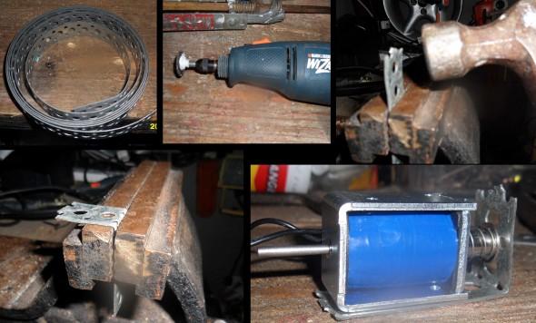
As you may have noticed from the video, the Solenoids strike the object, in this case a drinking glass, quite well. The issue is; when the voltage is removed from the coil and the magnetic field collapses, the striking mechanism fires out the back end of the Solenoid, not good. This can be overcome quite simply I’m sure, I will have to make up a bracket for each Solenoid with something physical behind the striking mechanism to prevent this issue.
Houston… We have a solution…
The solution I came up with was to make some L brackets out of metal strip that I had lying around in my box of tricks and to attach these to each Solenoid. It was necessary to have some cushioning on the L bracket directly behind the Solenoid pin to deaden the sound as the pin retracts and hits the L bracket, this is not shown but was done by simply wrapping the L bracket with electrical tape.
Electronic Circuit
Now that I have modified my Solenoids I need to design a circuit that will allow me to drive these via the 5v trigger signals from the Arduino’s digital outputs.
Some basic electronic theory
The Arduino’s digital outputs produce 5v (volts) and are limited to 40mA (milliamp) of Current (I). The issue with this is that my Solenoids run on 12v (volts) and draw 320mA of Current (I) each. Obviously the Voltage and Current requirements of my Solenoids out way the specifications of the digital output pins of the Arduino, so…. What we need to do is to connect an external power supply to the Solenoids and to use the Arduino digital signals to switch this voltage supply on and off as required.
Electronic design
With the specification of my Solenoids in mind I have an idea of how to switch the voltages on and off using a 5v trigger signal from the Arduino. Indecently, 5v trigger signals are widely used as automation signals in electronics, and are referred to as Logic Level Signals.
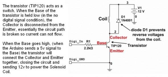
When working with electronic design, which is a large part of what I do, I like to create the circuit “virtually” in software before purchasing any parts. This process helps me to speed up production time and to reduce costs as it allows me to prototype and test my designs before even spending, or wasting, a penny. The image shows the circuit schematic that I have designed for one channel, we need 10 of these, one for each Solenoid:
Prototyping the electronic design
With my circuit designed and tested in software the next step is to create a physical prototype for testing. This step is almost always necessary and ensures that we don’t waste time developing a circuit that may not work correctly, even though it works 100% in software, there are no guarantees that this will translate 100% to the real world.
In this prototype there are more steps involved than usual circuit design; I will have to do more than I would for most prototypes as I am working with the Arduino, Max/MSP and the electronic circuit connected to a Solenoid. To simplify things a little I will be prototyping a single channel only, the resulting circuitry can then be translated to the 10 channels when the bugs (hopefully none) are ironed out.
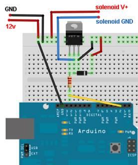
Step 1: Breadboarding
The first step in prototyping was to make the electrical connections on a Breadboard with the devices and to connect this to the Arduino.
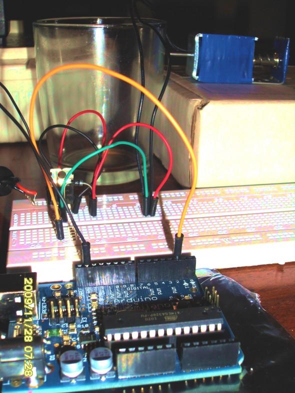
Step 2: Arduino and Max/MSP
The second step was to connect the Arduino to the computer, upload the program (Sketch) to the Arduino boards memory which allows communication between the Arduino and Max/MSP and to write a simple Max/MSP patch to send a digital pulse via the Arduino onward to the Solenoid driving circuit via Digital output pin 2. The prototype works very well, not bad for a days work, I’m happy and I have high hopes for this piece. Check out the Arduino test movie for the initial test:
PCB Design Process
With the circuit designed and tested in software and breadboarded and tested in real life it is time to bite the bullet and make the damn thing.
PCB Computer Aided Design
The first process is to use a Computer Aided Design software to recreate the circuit in its entirety and to use the same software to convert the schematic into a PCB Layout. For this I used a basic but useful pcb software named “PCB Wizard”. Ordinarily I would use either EagleCAD or Sprint Layout, both are very good PCB layout softwares. It was necessary to ensure that the footprint of the TIP120 matched the footprint of the part on the PCB to do this I used the datasheet
The PCB design look something like this:

PCB Manufacturing
There are many ways to manufacture Printed Circuit Boards, ranging from the expensive to the not so expensive, and over the years I have tried just about every form of PCB Manufacturing with varying degrees of success. In this section I want to run you through my current method: Toner Transfer.
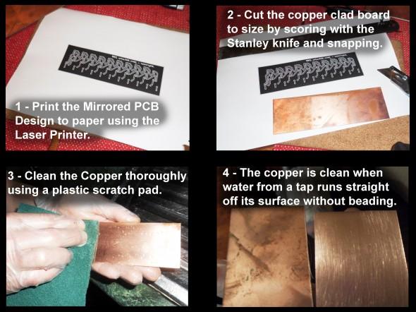
Toner Transfer
The basic premise behind Toner Transfer is that one can employ Laser Printer Toner, which is basically a plastic based material that forms the “ink” in this technology, and transfer the Toner from a sheet of paper to a bare Copper Clad board. The Toner is adhered to the copper surface using a combination of heat and pressure and the result is a layer atop the Copper that is resistant to chemical etchant/s. For this method to work you must use a Laser Printer and a certain type of paper.
Paper Types
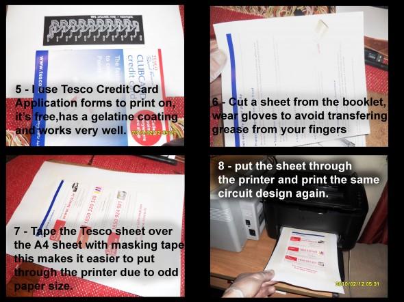
There are commercial papers available that make use of Toner Transfer such as this, however, this is a fairly expensive solution.
I have found a perfect replacement paper that is completely free: Take a trip to your local Tesco, at the counter you will find an array of advertisement documents for their Car/Pet/Home Insurance and their Application Forms for their own Credit Card. This paper is perfect for Toner Transfer as it has a Gelatine coating which assists in adhering the paper to the board and, since it is Tesco, I get a warm sense of anarchist pleasure in taking something back from the large multinational freight train. Sad, I know, but I digress.
Alternatives to Tesco paper would be pretty much any “shiny” magazine paper, although you may have to experiment to find one that works for you. Anyway, on with the show:
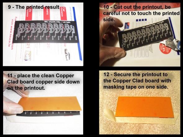
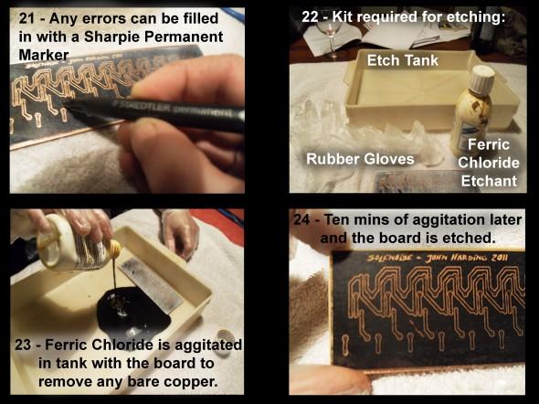
The Process
Rather than type the process in full I have chosen to create a series of noted images for your reference, a graphical montage if you will. Hopefully this can be easily followed, if you have any questions please let me know.


Soldering
The last stage that was completed on this project was the creation of a PCB which was hand made and drilled following the design process discussed, the next step is to permanently fix the electronic components to the PCB using molten silver “solder”. If you are interested to learn the technicalities of soldering you can read about it here.
Locating Components
The first step was to print out the circuit diagrams and part datasheets to use as a graphical reference to assist in locating the components on the PCB. The component legs are pushed through the holes that were drilled in the PCB and soldered to the copper pads to make a permanent electrical connection.


LED’s to assist whilst testing
I need some way to visually test the output voltages from the circuit, I could connect all 10 solenoids at this point but it’s rather unwieldy due to the sheer amount of wiring and in addition it is time consuming to connect all 10 solenoids each time I am working on the software design (more on this later)
For this task I have chosen to connect an LED ( light emitting diode ) to each output so that when voltage is being sent to the output (where a solenoid would normally be connected) then the LED on that channel will be lit. It should also prove to be visually quite interesting and, since the housing I intend to use is clear plastic, they may be left in situ.
Electronic considerations
LED’s come in many forms and colours but most happen to run on low voltages of less than 5v, generally 2v or 3v. The output of my circuit is actually providing 15v to each output, needed to power the solenoids, and this is much too high for an LED. If I were to send 15v to the LED it would light very briefly, and brightly, and would be followed by a small explosion and an awful burning smell.
I need to drop the voltage output so that is within the range of the specification of my LED’s. To do so firstly I grabbed the datasheet and noted the two most important specifications of my LED’s : Voltage (v) and Current (I)
In the case of my LED’s Voltage (v) specification is a value of typical 2v and maximum of 2.5v, Current (I) is 30mA (Milli Amp) max.
Chosen Values
To stay within a safe range of the specification I have chosen the following values:
Voltage 2v, Current: 20mA
From this you may have noticed that I have dropped the current by 10mA from the specification, the reason for this is that this is a Maximum specification, meaning the LED would likely fail at this Current. It is perfectly ok to drop Current from the specification a little, it merely means that the LED’s may be a little less brightly lit than using say 25mA but it has the advantage that they should not burn out as we are well below their specified limit.
So, how exactly do you drop voltage?
To drop Voltage from 15v that we have, to 2v that we need for each LED we use an electronic component called a resistor. We need to calculate the correct value however, to do so we use the following calculation:
R = (VS – VL) / I
R= Resistance
Vs = Supply Voltage (15v)
Vl = LED Voltage (2v)
I = LED Current (20mA, or 0.02A) [A = Amp, mA = MilliAmp, 1A = 1000mA]
R = (15-2)/0.02
R = 13/0.02
R= 650 Ohm
So, to run our LED’s in the above specification we need a 650ohm value resistor for each LED, however, resistors only come in certain values, the nearest standard value is 680ohm which is close enough.
As an alternative to the above calculation we could use a pre-built resistor calculator such as this.
Wiring the LED’s and housing the Circuit
As it turns out I didn’t happen to have any 680Ohm resistors in my stock, I did however have 330Ohm ones. Two resistors added together in series essentially means you can add the resistance values, so two 330Ohm resistors in series with one another would equate to a total resistance value of 660Ohm, which is very close to our ideal value of 650Ohm taken from the previous calculation, so that’s what I did. The final stage in the electronic build was to house the electronics within an enclosure, for this I chose a tupperware container. It is large, low cost, water-tight and made from clear plastic so I can show off all the beautiful components which will be nicely lit by the newly added LED’s.


Software Outlined
The elements which make up the programming/software side of this installation are graphically outlined as follows:

Starting from the top level we have a Lemur multitouch interface which will be programmed to allow the MIDI Clips in Ableton Live to be triggered by touching areas on the Lemur screen. I will have to create two parts for this: A graphical button layout which resides on the touch screen and I will have to hack Ableton Live to accept OSC data (which it doesn’t as standard). I am leaving this part to last.
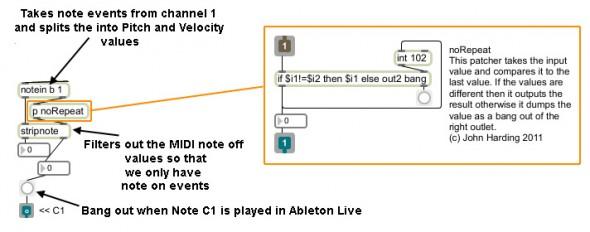
Ableton Live clips contain MIDI data, this MIDI data is internally routed to Max/MSP via MIDIYoke and custom software is written to transform the MIDI note on note off events into data that can be used to individually trigger the Solenoids via the Arduino and the custom designed electronic PCB (detailed in previous posts)
The following video is the result of this mornings programming work: MIDI Parsing (turning MIDI Clip Data from Live into separate bangs in Max). These events will be further transformed into a format that Arduino can understand so that we can trigger the Solenoids via Ableton Live.

Stage Two
With the MIDI routing complete the next stage is to write a Max/MSP patch that will convert these “bangs” into trigger signals that Arduino understands. To begin with I started with a patch called Maxuino v007 which is designed to allow transmission to and from the Arduino from within Max/MSP using the Firmata protocol. This patch is actually quite buggy and had to be re-programmed and heavily modified by me due to errors in the ordering of messages and general poor data handling, anyway I will spare you the boring detail. The following images outline the final program including the midi parsing that was discussed previously.


Stage Three
With the coding complete the ten solenoids were connected to the circuit for the first time. To say this was a nervous moment would be a serious under-statement considering that the schedule for Imagine Create has been out for some time now and if it fails I’m up the proverbial creek without a paddle. The final thing to do was to create some MIDI Clips for Ableton so I can send some data to the Solenoids. The following video is the result of the initial test: IT LIVES!
Stage Three Point One: Testing, Breaking and Fixing
One would be forgiven for assuming that the Solenoid software was finished and I could have moved on to the next and final stage of programming the Lemur touch interface to provide clip triggering, one would be wrong.
When working with Max/MSP or any other programming language for that matter there is a logical way of working, it goes something like this:
Get It Working (done)
Run it under severe stresses and all conceivable conditions until it breaks
Find out why it has broken
Fix it
Repeat and repeat until it no longer breaks
A short time after filming the initial test yesterday evening: IT LIVES! I decided to run some stress testing using the above methodology. After a short time it broke. During the upcoming Imagine Create festival I am providing lead technical direction, which means I don’t have time to keep coming to the installation to reset it, it needs to be reliable. During the stress testing I found a range of issues with data handling mainly due to coding errors by the makers of Maxuino 007 and some were hardware related (USB Driver update required).
The processes to fix the issues I encountered are graphically outlined for your reference:
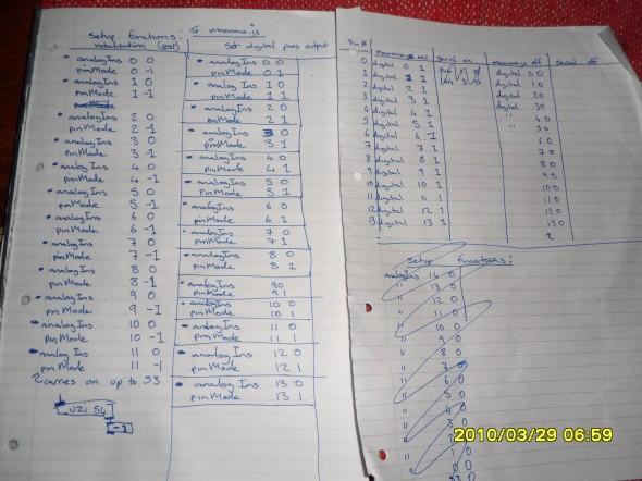
The first process was to reverse engineer the data values that Firmata expects to receive in order to switch on or off the various pins on the Arduino. To get these figures I had to view both the Firmata documentation, the Firmata code and the latest Maxuino 009. If you are wondering why I didn’t just use the latest Maxuino 009 then the reason is this; it is more complex than it needs to be, and also has its own set of unique bugs to overcome, it is far better in my opinion to begin from a working version (that I have now) and incorporate positive elements from the newer Maxuino release and streamline the code to my specific needs.

Almost the entire patch had to be reprogrammed in one form or another today, the above graphic outlines the main elements that were added and or changed.
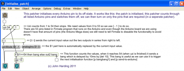
One of the issues I was having was with initialisation of the Arduino boards’ pins. On the Arduino we have to tell it to turn off a pin otherwise it can act weirdly; an error known as “floating pins”. In this case the pins have a certain amount of voltage flowing through them and this can cause data errors. The patcher [p initialise_patch] was created to solve the initialisation issues with the values that were gathered from the reverse engineering that was noted earlier. See the above graphic for details.

The patcher bangbang1, sends a series of "1"s to switch on all the digital pins
[Bangbang1] shown above takes its input as a bang from [p initialise_patch] and essentially switches all of our digital pins (via [send-to-arduino]) on after the initialisation has completed. For more detail see the graphic.

The [send-to-arduino] patcher is next in the initialisation chain and essentially provides the following function:
Firstly it turns off Analog input pin 1 then it turns on the Digital output pin 1, it completes this in a stepped fashion one pin after the other until all required Analog pins are switched off and all relative Digital pins are switched on. The reasoning for turning off the Analog pin before turning on its relative Digital pin is the same as before; to avoid “floating pin” errors.

You may remember from the MIDI_parsing patch that was mentioned earlier that I had created a function to remove the possibility of repeating values. I had overlooked one issue though: MIDI Velocity values range from 0 to 127. I was putting a starting value of 108 into the [int 108] which would cause an error if we happened to be using a MIDI velocity of 108 (no data would pass in this condition). To overcome this I changed the value to 129 which is above the range of MIDI Velocity data, meaning that this function will always pass the first value regardless of its value, and would still provide its functionality of removing any repetitions thereafter.

The final modification I have made today is to completely change the [arduino] patcher to [arduino_java]. Both of these patchers provide the functionality that send the data to the Arduino board, but as I had mentioned previously the [arduino] patcher has some issues with poor data handling resulting in serious errors. To overcome this I have made the patcher [arduino_java] which incorporates the Java code from Maxduino 009 to overcome the data handling issues.
The Result?
The result of all these changes is collectively huge, the patch can now handle great stress and fast repetitions without crashing, indeed I have yet to break it so I believe my job here is done for now at least.
The Interface
Below we can see the finalised interface which was developed in JazzMutant's Lemur. In usage this interface requires no explanation each coloured cell is a pre-composed sub-rhythm and the user can choose to mix and match these sub-rhythms in order to build up a percussive performance. The white cells allow the user to play the Solenoids directly if they so wish.

The finalised touch interface
The Aftermath
During the Imagine Create festival the system was installed into a stairwell and the attendees had a huge amount of fun playing the space as an instrument. Due to my schedule as technical director of the festival I didn't have a spare moment to capture any audio/visual references myself unfortunately, however, I did receive in the mail a really nice poem from one of the users; Mr. R. Mc Clelland, as seen depicted below. I was very touched by this I must say, if you're out there thank you Mr. Mc Clelland.
I do intend to revisit this project in future, and will be sure to get audio/visual references next time!
