Project Ninbendo Status: in Progress.
The concept behind Ninbendo is to create an audio/visual Nightclub Entertainment System, or NES for short.
Vintage Nintendo games are playable by the "clubbers" frequenting the venue, projection mapped to a large 80s style screen
Sounds fairly pedestrian right? Well....there are a few of catches...
Catch One: the projected imagery is constantly moving, through some analysis of the live audio stream and some clever coding the imagery dances in time to the music, moving and dancing making playability difficult.
Catch One point one: I have complete control over just how much it dances, via a custom MIDI controller built from an old Nintendo, we'll make some judgements based on the extent of your inebriation. This will be linear relationship: the more worse for ware you appear, the more difficult we will make it. Further details of the MIDI controller will follow.
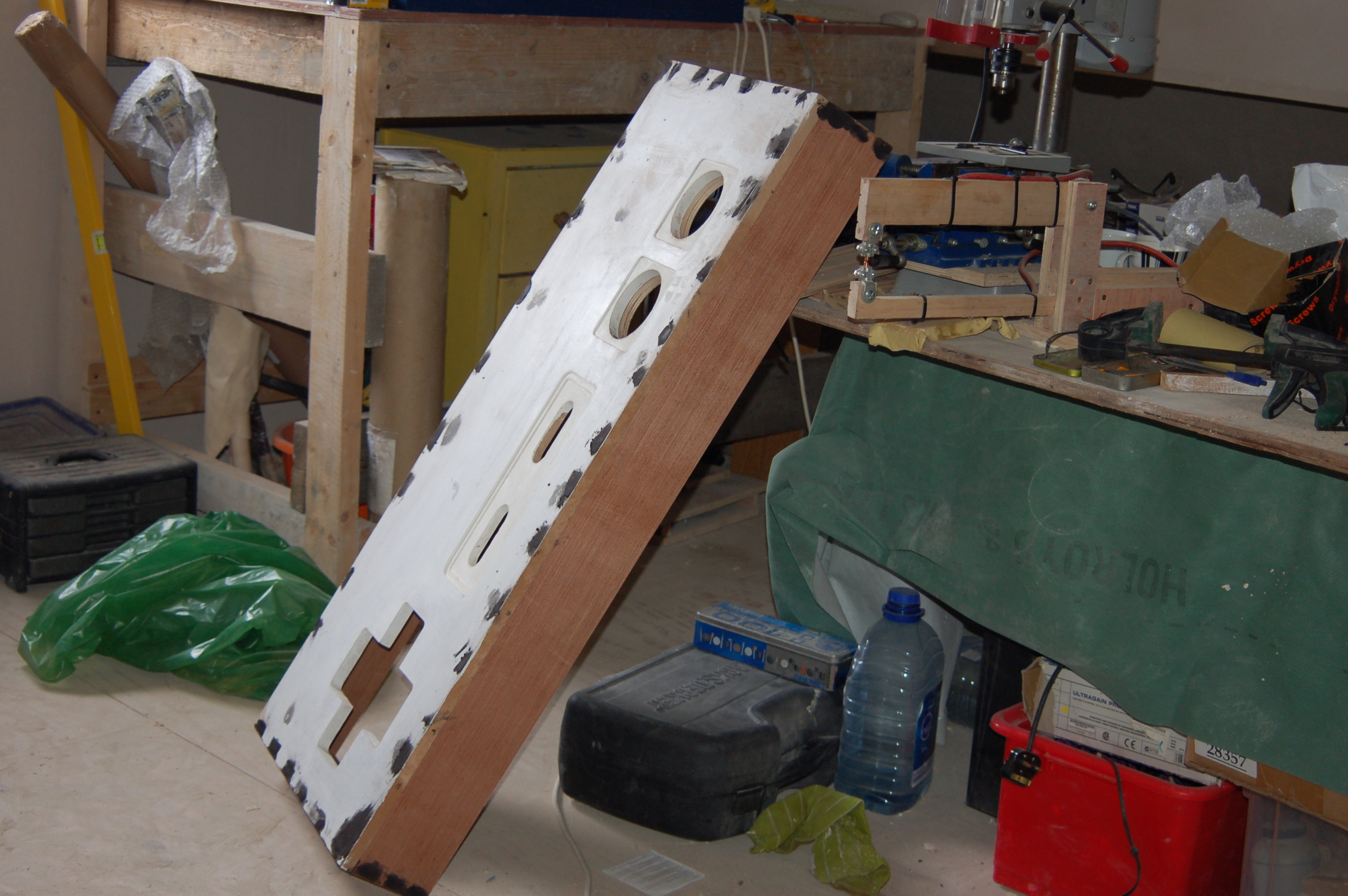
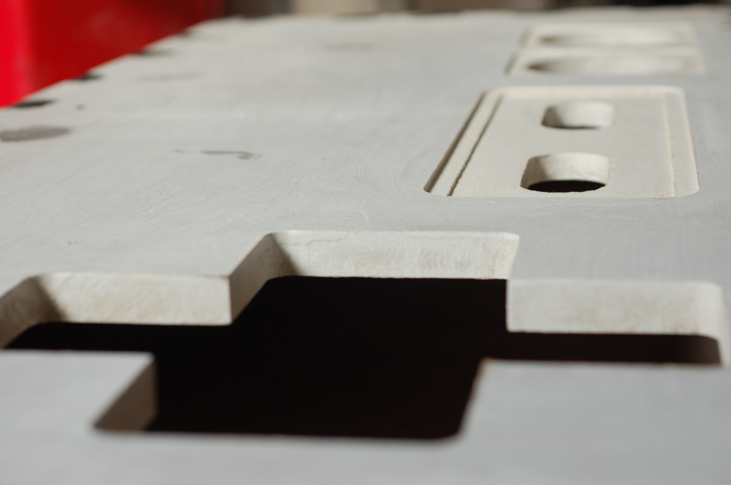
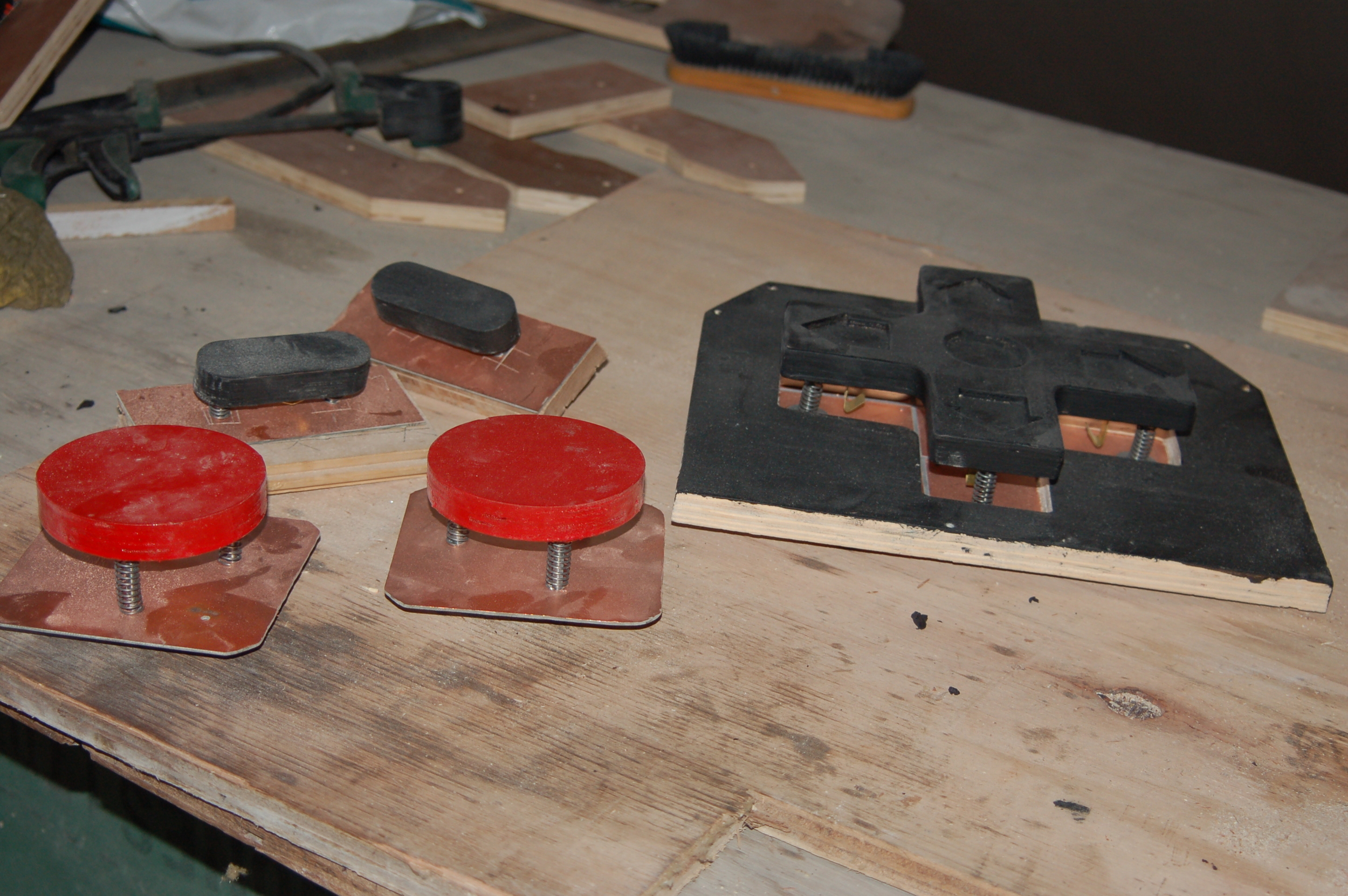
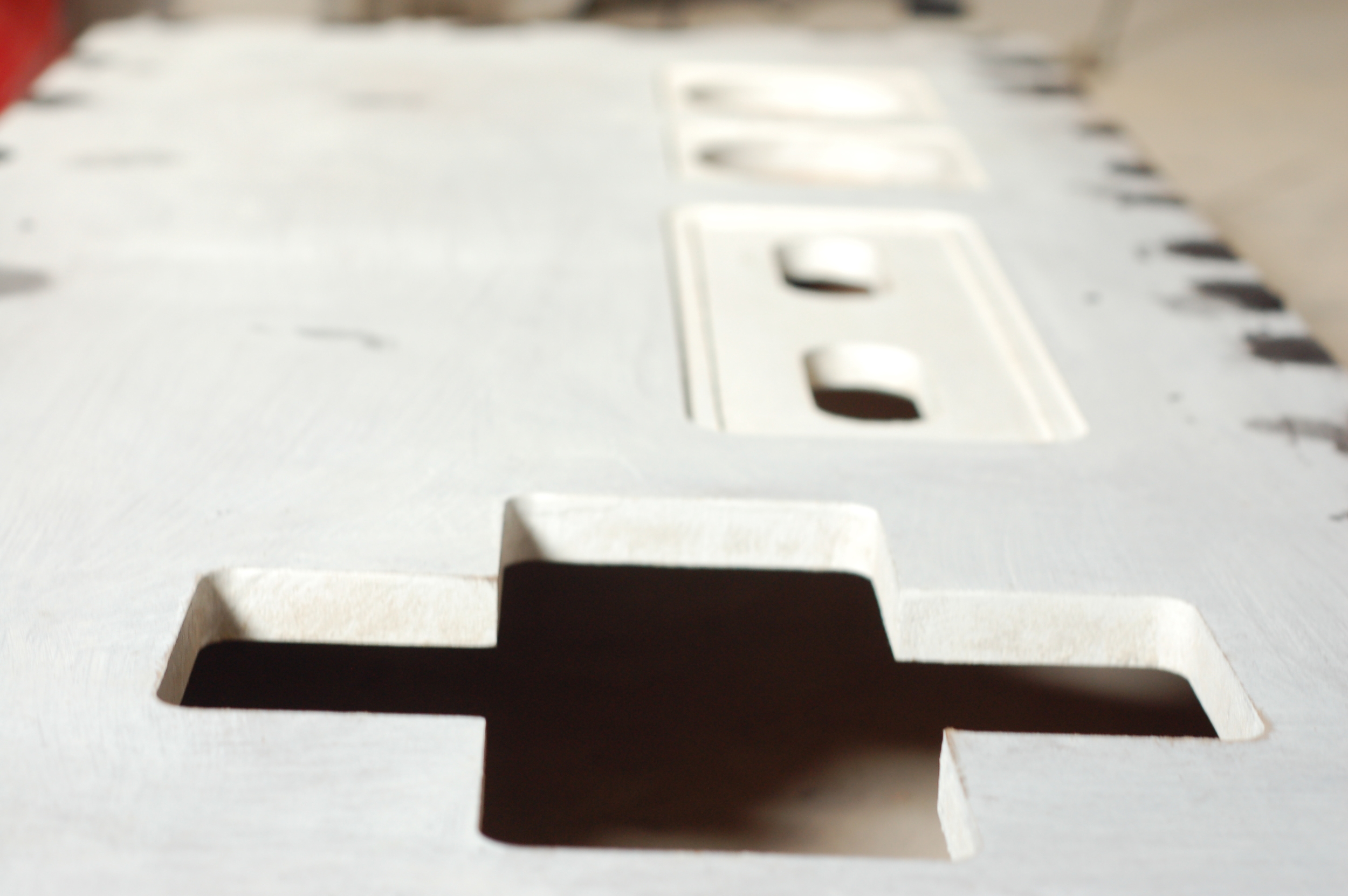
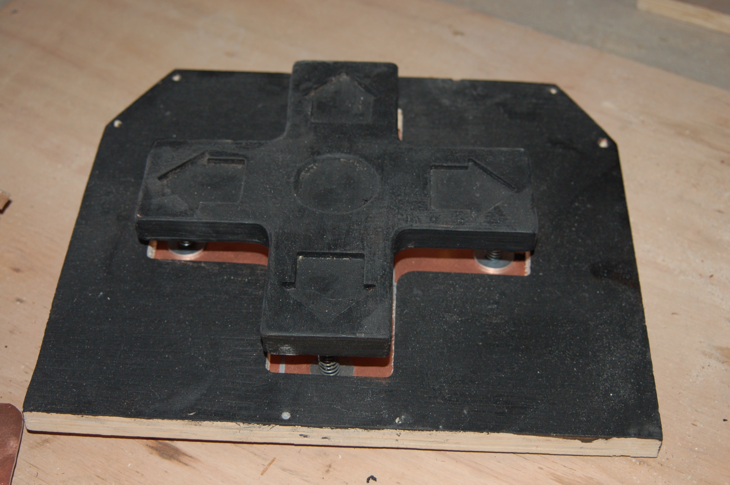
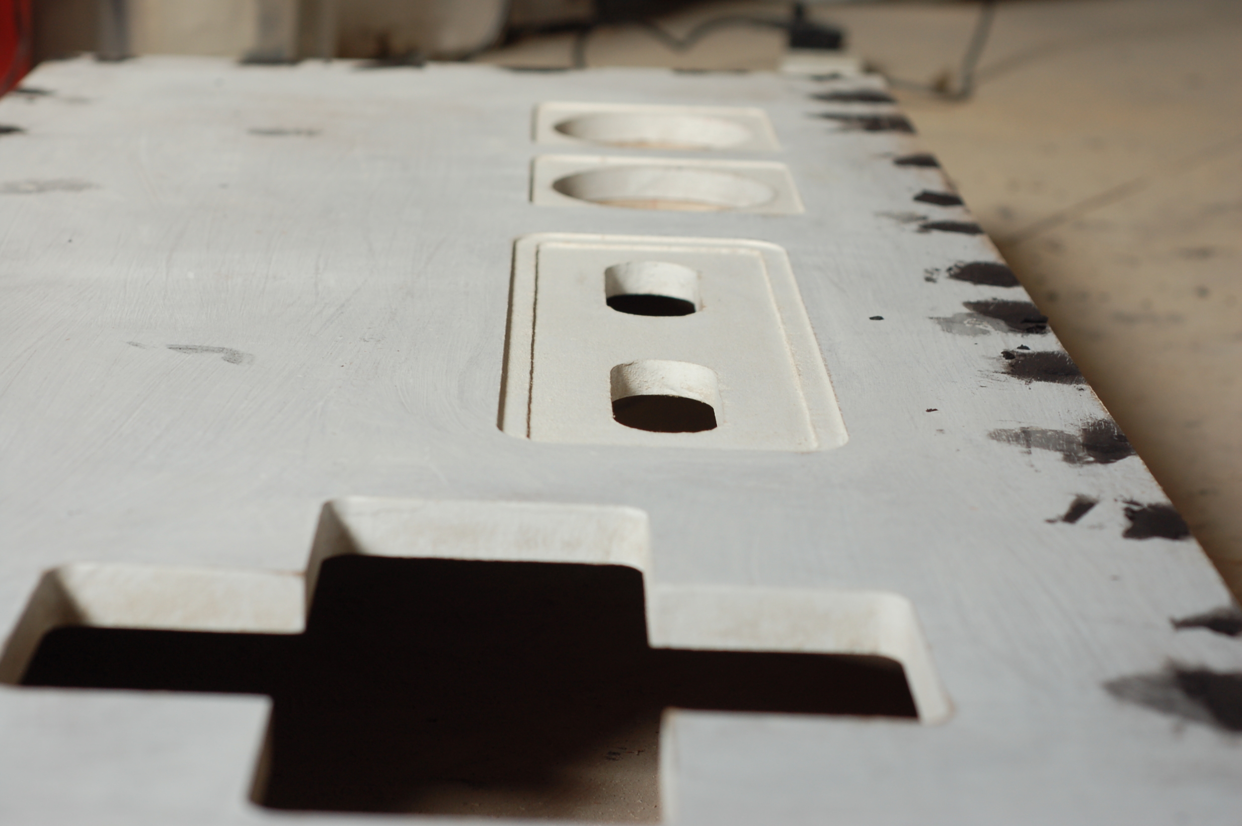
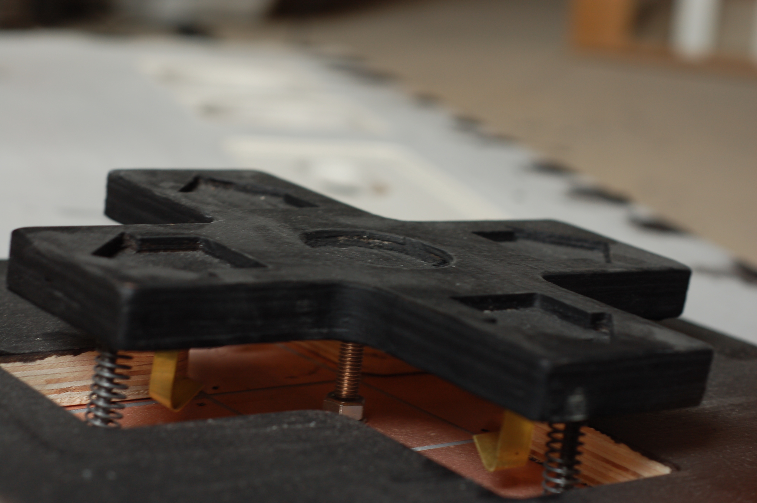
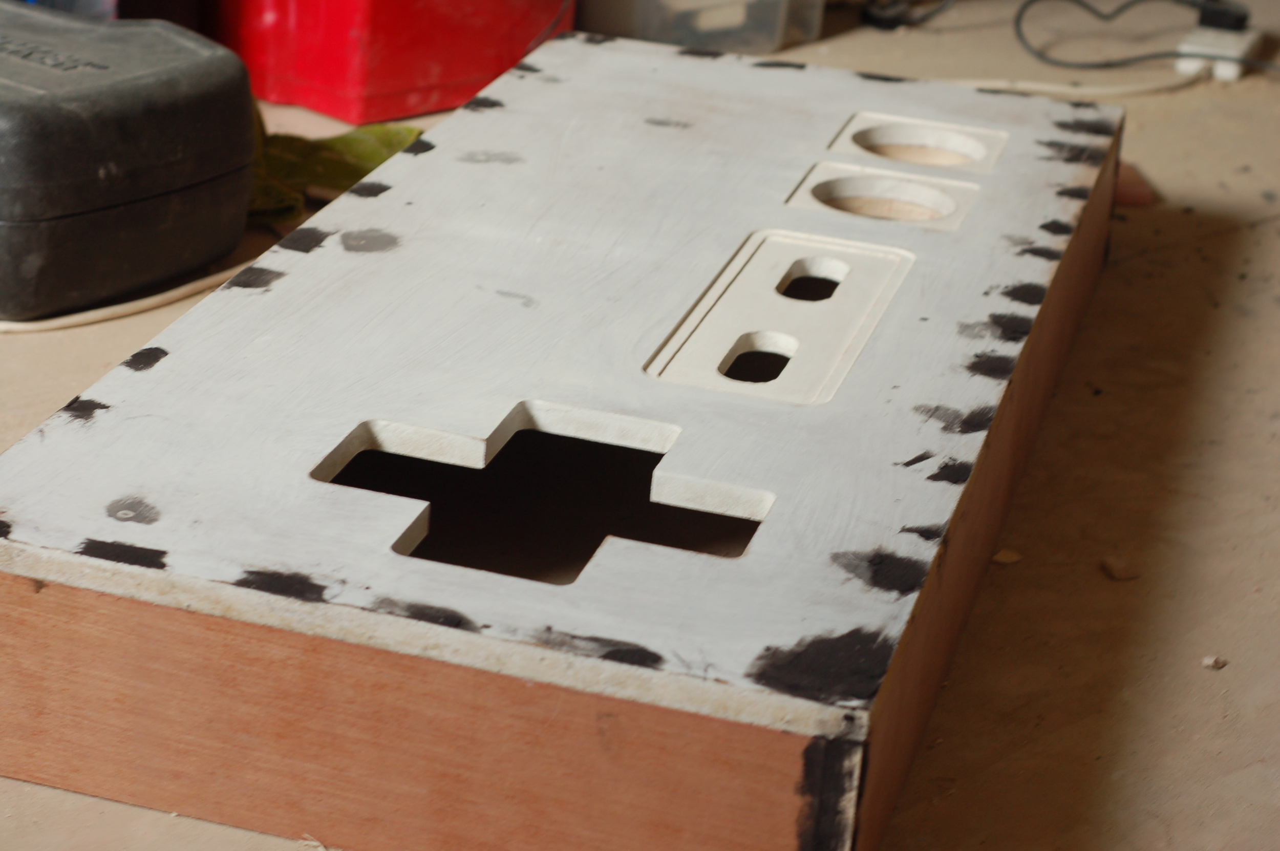
Catch Two: the controller is rather large, 1.2 meters in width to be precise. Below we can see a rough idea of the layout. The buttons were cut by CNC and the remainder is under construction. This will be a fun one...

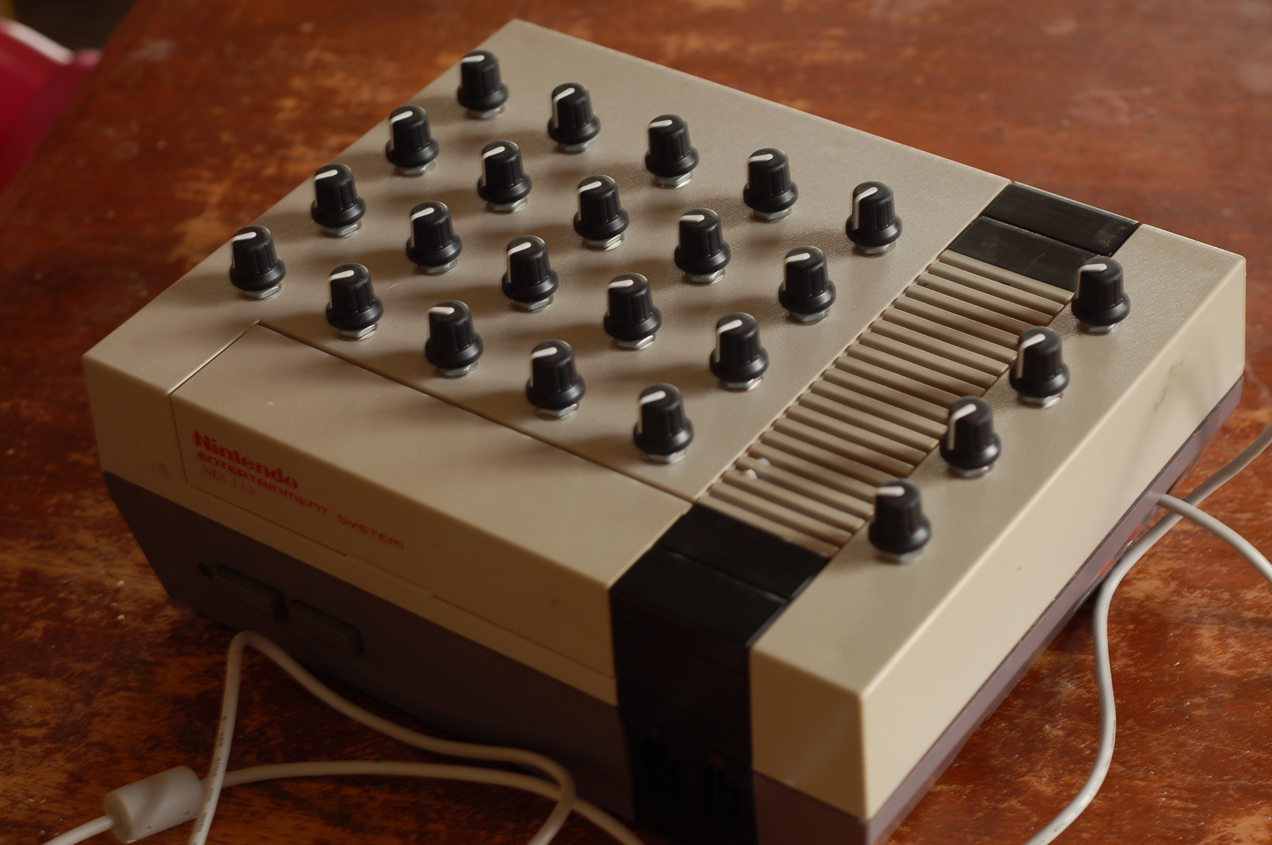
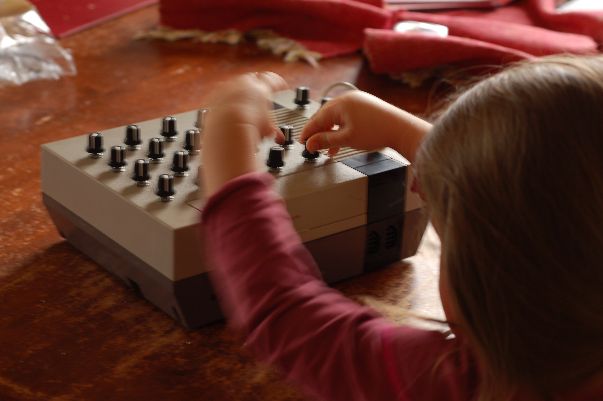
The "MIDI" Controller
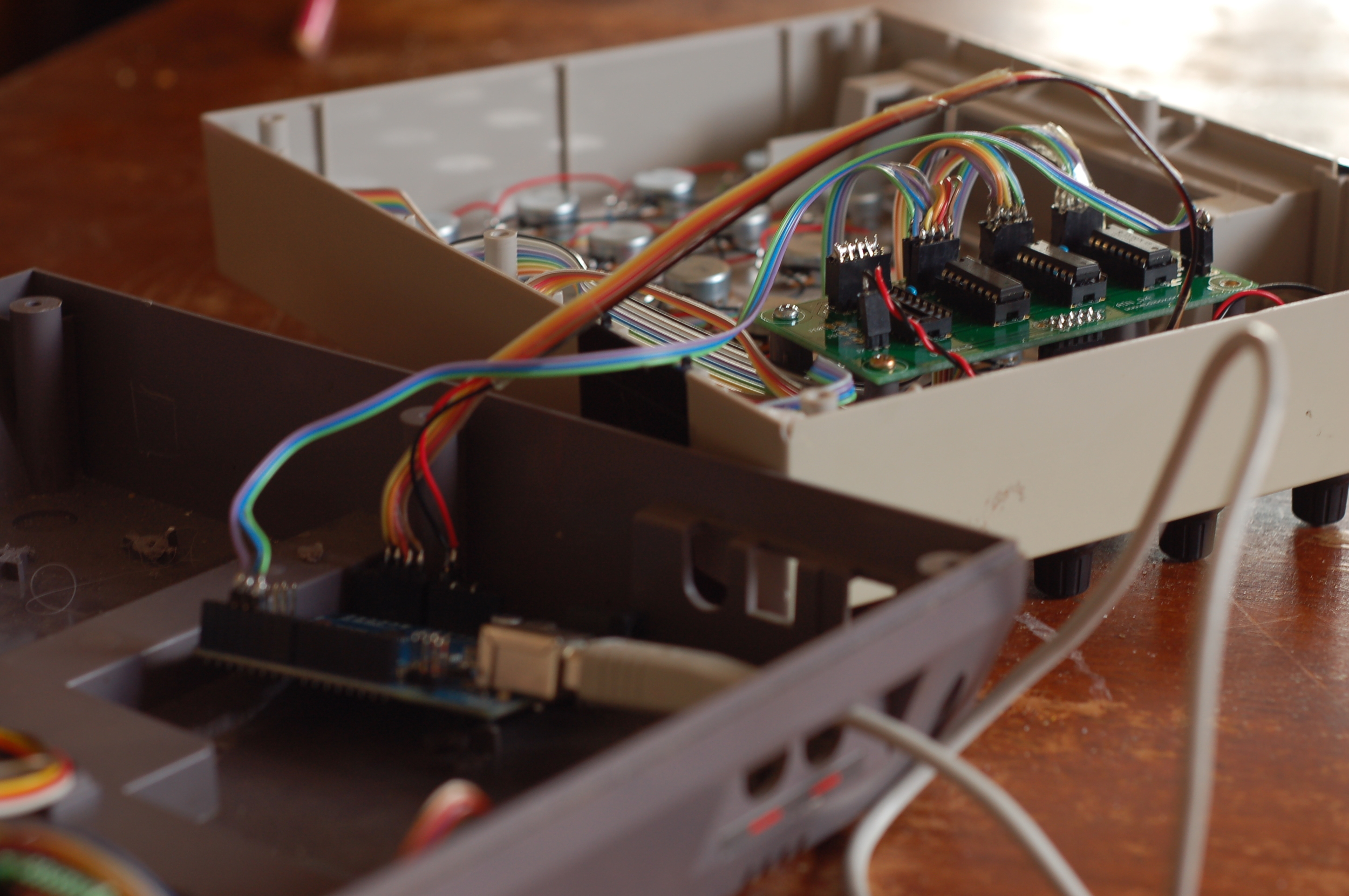
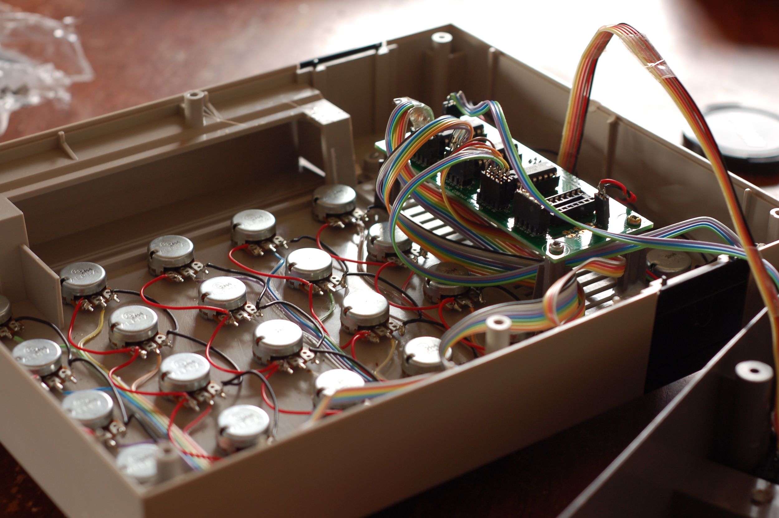
For this project, I thought it would be nice to have a custom controller for the person (me) operating the video transformation. There are various aspects that need to be controlled during performance related to the manipulations of the video, and whilst it would have certainly been easier to use an off the shelf solution (i.e. a MIDI Control surface) I felt that something more fitting was in order. After scrounging around ebay for some time I managed to find a non-working Nintendo NES that I gutted internally and retrofitted it with 24 potentiometers, a mutliplexing circuit and an Arduino UNO. A custom application was written in Max/MSP to convert serial data from the interface into MIDI CC (Control Change) commands which can in turn be used to control any MIDI capable software or hardware. In my implementation I can also route the MIDI CC data internally via the IAC Driver on mac osx to control other inter-applications such as Ableton Live for instance.
Coding
Below is the basic Arduino coding example. The multiplexing functionality has been left in its non optimised state in this example, for clarity. When researching the topic of Mutiplexing inputs I found that some examples were unnecessarily complex. It really is just simply counting through inputs in binary....
/* ------------------- NINBENDO MIDI------------------------
Code to allow 24 pots to be read and distrubuted to Max/MSP via USB Serial.
Readings are transmitted on request, Max sends a request 'r' to Arduino to request
pot readings, when arduino gets this 'r' message it scans through the potentiometers one by one,
in binary (via the multiplexers) and sends the readings to max.
Max then converts the messages into MIDI CC messages and can transmit these MIDI
messages to other applications (e.g. Ableton Live) via the IAC driver or MIDI Yoke,
or to external MIDI capable devices via a MIDI output interface
*/

//note: not well optimised but easy to understand, direct port manipulation would be much faster, loop statements could be much faster also.

//John Harding - 2015 - Steal this code //


int ax = 2; //digital address pin
int bx = 3; //digital address pin
int cx = 4; //digital address pin

byte data; //storage for pot readings

//int numPots = 24; //number of pots to read, not used yet

void setup() {
  //set the digital address pins as outputs
pinMode(ax, OUTPUT);
pinMode(bx, OUTPUT);
pinMode(cx, OUTPUT);

Serial.begin(115200);
}

void loop() {
  if (Serial.available() > 0) {
        if (Serial.read() == 'r') { // If an 'r' is received then read the pins

           for(int i=1; i <=3; i++) { //scan through the three multiplex IC's

     //set the control pins on the multiplexers.

    digitalWrite(ax, LOW); //0 in binary 000
    digitalWrite(bx, LOW);
    digitalWrite(cx, LOW);
    delayMicroseconds(50);
    data = (analogRead(i)) /8;
    Serial.write(data);
    //Serial.print(" "); //write a space (10 in ascii) to the serial port
    delayMicroseconds(50);

    digitalWrite(ax, LOW); //1 in binary 001
    digitalWrite(bx, LOW);
    digitalWrite(cx, HIGH);
    delayMicroseconds(50);
    data = (analogRead(i)) /8;
    Serial.write(data);
    //Serial.print(" "); //write a space (10 in ascii) to the serial port
    delayMicroseconds(50);

    digitalWrite(ax, LOW); //2 in binary 010
    digitalWrite(bx, HIGH);
    digitalWrite(cx, LOW);
    delayMicroseconds(50);
    data = (analogRead(i)) /8;
    Serial.write(data);
    //Serial.print(" "); //write a space (10 in ascii) to the serial port
    delayMicroseconds(50);

    digitalWrite(ax, LOW); //3 in binary 011
    digitalWrite(bx, HIGH);
    digitalWrite(cx, HIGH);
    delayMicroseconds(50);
    data = (analogRead(i)) /8;
    Serial.write(data);
   // Serial.print(" "); //write a space (10 in ascii) to the serial port
    delayMicroseconds(50);

    digitalWrite(ax, HIGH); //4 in binary 100
    digitalWrite(bx, LOW);
    digitalWrite(cx, LOW);
    delayMicroseconds(50);
    data = (analogRead(i)) /8;
    Serial.write(data);
   // Serial.print(" "); //write a space (10 in ascii) to the serial port
    delayMicroseconds(50);

    digitalWrite(ax, HIGH); //5 in binary 101
    digitalWrite(bx, LOW);
    digitalWrite(cx, HIGH);
    delayMicroseconds(50);
    data = (analogRead(i)) /8;
    Serial.write(data);
    //Serial.print(" "); //write a space (10 in ascii) to the serial port
    delayMicroseconds(50);

    digitalWrite(ax, HIGH); //6 in binary 110
    digitalWrite(bx, HIGH);
    digitalWrite(cx, LOW);
    delayMicroseconds(50);
    data = (analogRead(i)) /8;
    Serial.write(data);
    //Serial.print(" "); //write a space (10 in ascii) to the serial port
    delayMicroseconds(50);

    digitalWrite(ax, HIGH); //7 in binary 111
    digitalWrite(bx, HIGH);
    digitalWrite(cx, HIGH);
    delayMicroseconds(50);
    data = (analogRead(i)) /8;
    Serial.write(data);
    //Serial.print(" "); //write a space to the serial port
    delayMicroseconds(50);
     }
    }
  }
}
Circuitry
For those that have been paying attention you may have noticed me mention Multiplexing... What's that exactly? Well... The Arduino only has 6 analog inputs, meaning that in it's standard state I would be limited to reading six potentiometers (the rotary controls) This unit has 24. Mutliplexing allows us to scan through many inputs using binary counting to keep track of the pot/sensor we are reading at any one time, meaning we can use three analog inputs plus some digital outputs (3) to transmit the current binary count.
This process requires some external integrated circuits known as, yes you've guessed it: Multiplexers. In this case I employed a pre-built multiplexer circuit that I had to hand from my box of tricks, if you're interested the source is the AIN (Analog In) board for MIDIBox, this particular version is from SmashTV.
The circuit itself is really simple, the CD4051 multiplexers each can read 8 inputs, we can address the pins via three digital outputs and scan through the inputs one by one by counting to 8 (from 0 to 7) in binary. Data is then sent a byte at a time to Max. I am currently using only 3 of 4 CD4051's on this interface, as I only am going to read 24 potentiometers vs. 32 that the AIN board is capable of.
Max Coding
The Max/MSP interface is shown below graphically for reference. I intend to share this patch shortly but I have a few coding tweaks to add in the interim so will refrain from doing so for the time being. Hopefully what this does is fairly self explanatory, it replicates in software the "MIDI" interface, giving the user visual feedback as to the potentiometer states and also allowing routing to different MIDI destinations.

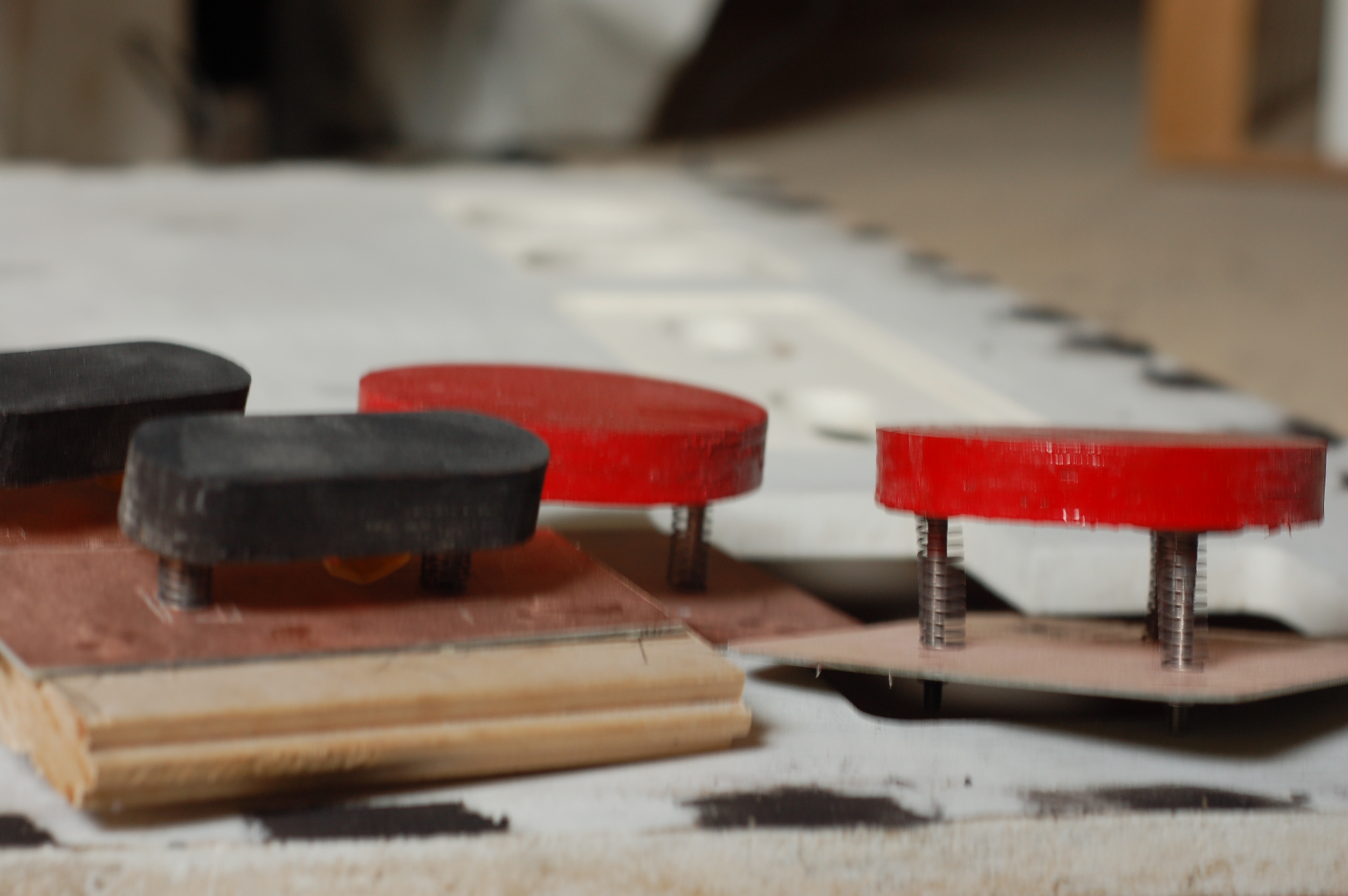
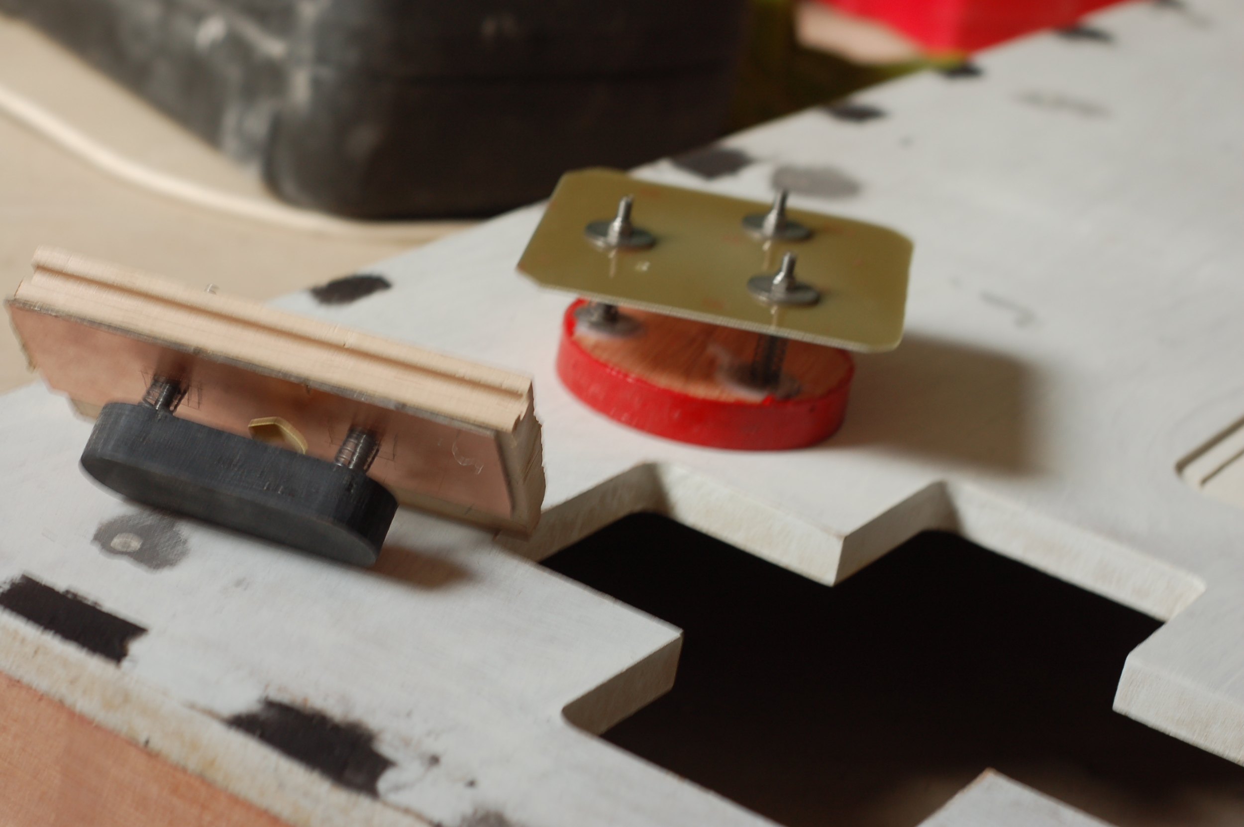
The Controller
The main controller has made some progress and will likely be completed in the next few weeks, here are some development pictures to keep you entertained.